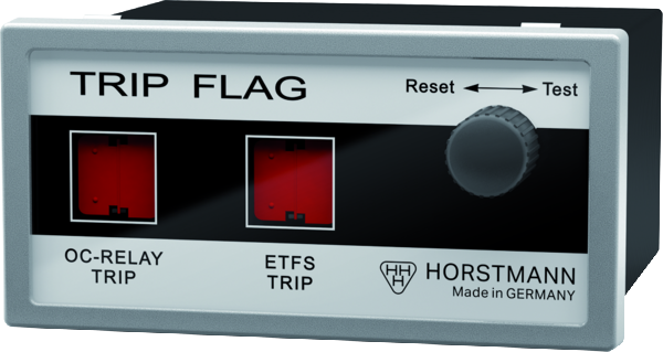
Trip Flag
indications. It is suitable for the trip display of CT powered protection devices with electrical impulse output.
In addition to the display, output relays are activated. Each output has 2 changeover contacts. The output contacts and the display are latching and are reset manually via a rotary knob.
The Trip Flag is suitable for protection devices from Woodward (WIC1, WIB1, WIP1).
For devices of other manufacturers the electrical impulse of the outputs of the protection relays needs to be 24 V DC and E ≥ 0.01 Ws.
- Suitable for connection to CT powered protection relays in gas-insulated medium voltage switchgears
- 2 drop indicators (black/red)
- OC relay trip: Overcurrent relay trip
- ETFS trip: External trip forced switch
- Controllable via electrical impulse output
- 2 changeover contacts per relay, self-holding
- Test / reset function for indicator and relay contacts via rotary knob
Technical specifications
| Measurement sensors | - |
|---|---|
| tI>> response delay | - |
| Threshold inequality | - |
| Trip current earth potential | - |
| Accuracy | - |
| Amount of channels | - |
| Indication | 2 trip displays (black / red) |
| Relay contacts | 4 |
| Remote contact | Potential-free contacts, bistable Contact capacity: 230 V AC/1 A/62.5 VA max. 220 V DC/1 A/60 W max. |
| Manual reset | --- |
| Remote reset | - |
| Automatic time reset | - |
| Reset via interface | - |
| Reset on current restoration | - |
| Reset on voltage restoration | - |
| Reset on restoration of auxiliary supply | - |
| Reset via Explorer Software | - |
| Internal power supply | - |
| External auxiliary supply | Electrical impulse, 24 V DC ≥0.01 Ws |
| CT powered | - |
| Housing | Polycarbonate, IP40 |
| Temperature range | -30 to +70 °C |
| Cable diameter | - |


