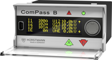
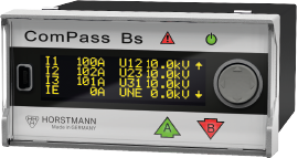
ComPass B 2.0
The ComPass B 2.0 is particularly suitable for use in those substations in a medium voltage network that feature a remote control connection. In addition to the short-circuit and earth fault function, ComPass B 2.0 supplies the collected measured values of current, voltage and power from the station for transmission to the control room. The PT-100 sensor measures the temperature, for example of the transformer or the transformer station. For all measured values limits can be defined, which can also be transmitted to the control room.
The voltage coupling/measurement is done via the capacitive VDS system and/or via resistive (ohmic) voltage sensors. With the simultaneous measurement, the voltage measurement of the VDS system can be automatically calibrated with the resistive voltage measurement. Up to four ComPass B can be connected to one set of resistive voltage sensors.
Equipment set includes:
- 1 display unit
- 3 single-phase current sensors
- Voltage coupling
- Clear fault indication and reading on-site: 2 directional arrow LEDs (A, B) and high contrast OLED display
- High-precision current and voltage measurement (0.5 %)
- Monitoring of the parameters voltage (V), current (I), load flow direction (A↑ or B↓), power factor (cos φ), power (P, Q, S), energy (E), temperature (T) and frequency (f)
- Suitable for all types of networks/neutral point treatments
- Earth fault detection with 6 different earth fault detection methods, also in combination
- Voltage monitoring with connection to capacitive and resistive (ohmic) sensors in one indicator
- Limit monitoring: V, I, P, Q, T
- ComPass Explorer Software: Commissioning and parameterisation via front accessible USB port
Your advantage
- Immediate detection of fault direction
- Immediate detection of limit violations
- Measured values available for SCADA and on site
- Automatic self-calibration of the capacitive voltage inputs, optionally with temperature compensation
Technical specifications
| Earth fault detection methods | Permanent, earth short-circuit, transient, cos ɸ, sind ɸ, pulse detection |
|---|---|
| Low-impedance/short-term low-impedance earthed | --- |
| Isolated earthed | --- |
| Resonant earthed | --- |
| Indication | LED status display; OLED display, directional arrows red/green |
| Measured values | Phase currents I1, I2, I3, IE with phase angle Phase-to-earth voltage V1, V2, V3, VNE and phase-to-phase voltage V12, V23, V31, VNE with phase angle Load flow direction A↑ or B↓ P, Q, S and cos φ (power factor) (P1,2,3, Q 1,2,3, S 1,2,3, cos φ 1,2,3 via RS485) Amount of active energy, separate for load flow direction A↑ or B↓, additionally per phase Operating current I1,2,3, S, P, Q, V12, V23, V31, Ø-vaule adjustable (1 – 60 min), I max. 24 h / 7 days / 365 days, maximum demand indicator Imax. LR , V12max LR, V23max LR, V31max LR, Smax LR, Pmax LR, Qmax LR, Tmin LR, Tmax LR (LR = last reset) Frequency f Temperature T |
| Short-circuit trip current | 10 - 2,000 A, self adjustment (200 - 2,000 A) |
| Response delay short-circuit | 20 ms - 60 s |
| Earth short-circuit trip current | 10 - 1,000 A |
| Response delay earth short-circuit | 40 ms - 60 s |
| Trip current transient method | 10 - 500 A |
| Trip current active current cos ɸ | 1 - 200 A |
| Response delay active current cos ɸ | 40 ms - 60 s |
| Trip current reactive current sin ɸ | 1 - 200 A |
| Response delay reactive current sin ɸ | 40 ms - 60 s |
| Trip current permanent earth fault | 1 - 100 % |
| Response delay permanent earth fault | 40 ms - 60 s |
| Trip current pulse detection | 1 - 200 A |
| Limit overload current | 5 - 1,500 A |
| Limit overvoltage | 100 - 200 % |
| Response delay overload current | 40 ms - 60 s |
| Response delay overvoltage | 40 ms - 60 s |
| Limit undervoltage | 1 - 100 % |
| Response delay undervoltage | 40 ms - 60 s |
| Limit active power | 1 - 30,000 kW |
| Response delay active power | 40 ms - 60 s |
| Trip current reactive power | 1 - 30,000 kW |
| Response delay reactive power | 40 ms - 60 s |
| Limit temperature | -40 to +85 °C |
| Phase currents | ±0,5 % (0 - 630 A) ±3 % (630 - 1,500 A) ±5 % (1,500 - 2,000 A) closed sensor type |
| Voltages | Up to 0.5 % in the range of 80 - 120 %/Vnom (resistive) |
| Relay contacts | 4 |
| Remote contact | Potential-free permanent or momentary contact (>1 s), bistable, NC or NO Contact capacity: 230 V AC/1 A/62.5 VA max. 220 V DC/1 A/60 W max. |
| RS485/Modbus-RTU | --- |
| USB port | --- |
| Binary inputs | 2 |
| Ethernet interface | - |
| Resistive | --- |
| Capacitive | --- |
| Manual | --- |
| Remote | --- |
| Software via USB | --- |
| Manual reset | --- |
| Remote reset | --- |
| Automatic time reset | --- |
| Reset via interface | --- |
| Reset on current restoration | --- |
| Reset on voltage restoration | --- |
| Reset on restoration of auxiliary supply | --- |
| Reset via Explorer Software | --- |
| Internal power supply | Long-life lithium cell, active flashing time >1000 h, >1000 display activations, shelf life ≥20 years |
| External auxiliary supply | 24 - 230 V AC/DC |
| CT powered | - |
| Housing | Polycarbonate, IP50 |
| Temperature range | -30 to +70 °C |
| Cable diameter | - |
- OLED display: easy to read in all lighting conditions
- Displaying the measured values and configuring via the display
- Rocker switch for easy handling
- Easy parameter setting and commissioning via USB port
- Input for PT100
- Reverse polarity protected plug-in terminals for quick and easy installation


")