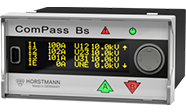
ComPass Bs 2.0
Fault direction indicator with monitoring and control function
The ComPass Bs 2.0 is particularly suitable for use in substations with a telecontrol connection for electrical energy distribution in the medium-voltage grid. In addition to the short-circuit and earth fault functions, the ComPass Bs 2.0 collects high-precision measured values for current, voltage and power from the station and makes them available for transmission to the control room. The transformer or station temperature can also be monitored via a PT-100 sensor. Limit values can also be defined for all measured values
, which can also be made available to the control room as alarms.
Voltage coupling/measurement takes place capacitively via the VDI system* and/or via resistive (ohmic) voltage sensors. With simultaneous measurement, the voltage measurement via the VDIS system can be automatically calibrated with the resistive voltage measurement. Up to four ComPass can be connected to a set of resistive voltage sensors.
The ComPass Bs 2.0 also offers a control function for switching two switching elements. A free assignment of six binary inputs, which can be combined with freely programmable logic (PLC functionality), allows the user to flexibly define switching conditions. The binary inputs can also be used to record any information, e.g. SF6 gas fault or HV fuse failure.
* VDIS according to IEC62271-213, current standard as of 08/2023
Product features
- For controlling a switch-disconnector or circuit-breaker remotely
- Freely assignable binary inputs for recording and transmitting relevant status information from the system/station
- Freely programmable logic for defining the switching conditions
- Clear error display and reading option on site:
2 directional arrow LEDs (A, B) and high-contrast OLED display - Highly accurate current and voltage measurement up to 0.5 % accuracy
- Monitoring of the variables voltage (U), current (I), load flow direction (A↑ or B↓ ), power factor (cos φ), power (P, Q, S), energy (E), temperature (T) and frequency (f)
- Suitable for all mesh types/star point treatments
- Earth fault detection with six different earth fault location methods, can also be combined
- Coupling to capacitive and resistive (ohmic) sensors
- Limit value monitoring and remote signaling: U, I, P, Q, T
- ComPass Explorer software: Commissioning and parameterization via front USB port
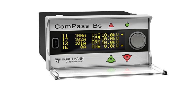
OLED display for good readability
Mini-USB port for easy parameterization and commissioning
Quick and easy to operate rocker switch
Indication of measured values and configuration via the display
Your added value
- Immediate fault direction detection
- Immediate detection of limit violations
- Availability of measured values in the control room and on site
- Automatic self-calibration of the capacitive voltage inputs, optionally with temperature compensation
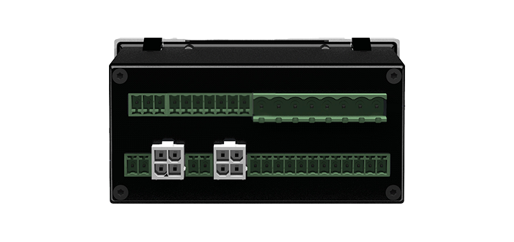
Six binary inputs
Reversible plug-in terminals for quick and easy installation
Technical data of the ComPass Bs 2.0
| ComPass Bs 2.0 | |
|---|---|
| Short-circuit indicator | ✅ |
| Earth fault indicator | ✅ |
| Earth fault location method | Continuous earth fault, earth short circuit, earth fault wiper, cos φ, sin φ, pulse location |
| Remote control | 2 switching elements |
| Logic/32 modules | ✅ |
| Measured values / display |
|
| I>> Response values Short-circuit current | 10 – 2,000 A, self-adjustment (200 – 2,000 A) tI>> Response delay: 40 ms – 60 s |
| IES> / IES>> Response values earth fault current | 10 – 1,000 A tIES> / tIES>> Response delay: 40 ms – 60 s |
| IET> Response values earth fault wiper method | 1 – 500 A |
| IEP> Response values active residual current cos φ / IEQ> Response values reactive current sin φ | 1 – 200 A tIEP> / tIEQ> Response delay: 40 ms – 60 s |
| ΔIE> Response values for pulse detection (clock stroke) | 1 – 200 A |
| UNE> Response values Permanent earth fault | 1 – 100 % tUNE> Response delay: 40 ms – 60 s |
| Limit value monitoring | |
| I> Overcurrent | 5 – 1,500 A tI> Response delay: 40 ms – 60 s |
| U> Overvoltage | 100 – 200 % tU> Response delay: 40 ms – 60 s |
| U< Undervoltage | 1 – 100 % tU< Response delay: 40 ms – 60 s |
| P> / P>> / +P> / -P> Active power | 1 – 30,000 kW tP> / tP>> / +tP> / -tP> Response delay: 40 ms – 60 s |
| Q> / Q>> / +Q> / -Q> Reactive power | 1 – 30,000 kW tQ> / tQ>> / +tQ> / -tQ> Response delay: 40 ms – 60 s |
| T< / T<< / T> / T>> Temperature | -40 °C to +85 °C |
| Measuring accuracy phase currents | Up to 0.5 % / 0.5 A closed sensor type, 1 % / 0.5 A divisible sensor type |
| Measuring accuracy voltages | Up to 0.5 % in the range 80 – 120 %/Un (resistive) |
| Display | LED error message and status displays (multicolor) OLED display (trilingual) |
| Remote notification / communication |
|
| Remote signaling contact | 4 permanent or wiping contacts, monostable, NC or NO contact Contact rating: 250 V AC/6 A; 30 V DC/6 A, resistive load |
| Binary inputs | 6, freely programmable, max. 30 V DC |
| Reset |
|
| Supply | |
| External auxiliary voltage | 24 V – 230 V AC / DC (±10 %) |
| Internal power supply | Long-life lithium cell, >1,000 h total flashing time of the LED, >1,000 display activations |
| Housing | Polycarbonate, IP50 |
| Temperature range | -30 °C to +70 °C |
All important documents for the device
Do you need additional information about our device? In our download area you will find all relevant documents such as brochures and product catalogs, technical reports, operating instructions and dimensional drawings (login required). Simply click on the download area to obtain the documents you require.
Matching articles
PERFECT MATCH
Here you will find the matching equipment set and accessories for this item. All components are technically matched to each other and guarantee optimum functionality. For customer-specific requirements and individual offers, please contact our sales department.
Equipment set
- 1 ComPass B 2.0 display unit
- 3 phase current sensors
- 1 Voltage signal
(Combination with phase current sensors possible: 3+1 or 2+1)
Other short-circuit and earth fault indicators
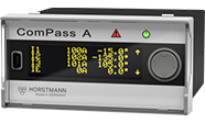
ComPass A 2.0
- Load current monitoring
- Detection of earth faults and short circuits for NOSPE/ KNOSPE networks
- Fault indication without directional information
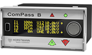
ComPass B 2.0
- Highly accurate monitoring
- Detection of earth faults and short circuits for all networks
- Directional fault indication
ComPass Bs 2.0
- Fault direction indicator with monitoring
- Detection of earth faults and short circuits for all networks
- Switching ComPass Bs 2.0 for controlling a switch-disconnector or circuit-breaker remotely
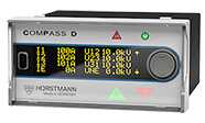
ComPass D
- Highly accurate monitoring for network analysis
- Earth fault and short-circuit detection in all network types with fault direction display
- Extended switching function and communication via Ethernet