Targeted troubleshooting in the distribution grid: Sigma series at a glance
Innovative solutions for complex networks: efficient troubleshooting with short-circuit and earth fault indicators from the Sigma series
Today’s distribution grids are increasingly complex due to the integration of decentralized feed-in points such as wind and solar parks as well as the growing demand for charging infrastructure for e-mobility, heat pumps and battery storage. Depending on the condition of the grid and the desired digitalization goals, it may make sense to supplement local grid stations with the targeted use of short-circuit and earth fault indicators from Horstmann’s Sigma series.
The Sigma series at a glance
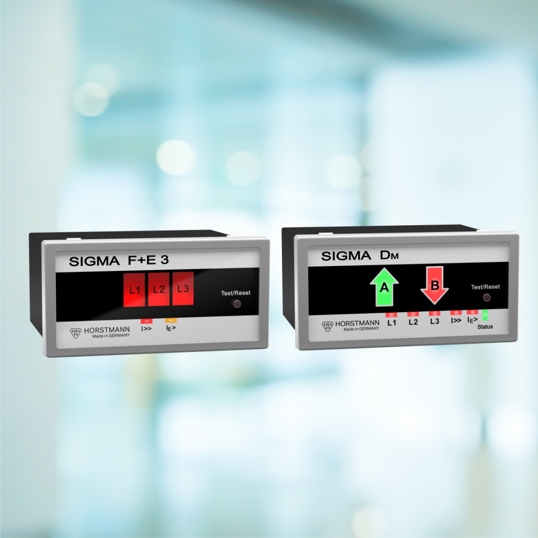
The Sigma series is the ideal solution for targeted troubleshooting in the distribution network. It enables phase-selective short-circuit and earth fault indication, optionally with or without direction determination. The Sigma series offers comprehensive support in all MV network types, particularly for earth fault detection, with special consideration of neutral point treatment. Several options are available for remote transmission. Installation is possible both in new systems with closed current sensors for every type of switchgear as well as retrospectively in existing systems, using separable current sensors for mounting around the MV cable.
Sigma 2.0 series
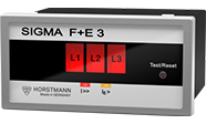
Sigma 2.0
- Phase-selective short-circuit indicator
- Clearly visible LED error display
Sigma R+D 2.0
- Corresponds to Sigma 2.0
- Earth short-circuit monitoring in low-impedance earthed networks (NOSPE) and isolated beam networks
- No false excitation due to harmonics
Sigma R+D 3.0 2.0
- Corresponds to Sigma R+D 2.0
- Extended setting options for the earth fault function
- Red LED I>> for short-circuit indication and yellow LED IE> for earth fault indication
All devices in the Sigma 2.0 series have remote signaling via relay contacts. They are self-powered and do not require an external auxiliary power supply as they use an internal battery to power the LED display, which does not need to be replaced.
Sigma 2.0 Series AC/DC
- Corresponds to Sigma 2.0 series
- Alternatively with capacitor buffering, no internal battery
- Auxiliary power supply 24V-230V AC/DC
Sigma L series
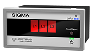
Corresponds to Sigma 2.0 AC/DC series
- With remote transmission via LoRaWAN radio technology
Star point treatments in medium-voltage distribution grids
The neutral point treatment of the medium-voltage grid determines the behavior of the grid in the event of an earth fault
- Low-resistance earthed – NOSPE, or short-term low-resistance earthed KNOSPE
- Resonant star point earthing – RESPE, compensated networks with Petersen coil
- Isolated systems – OSPE, without neutral point treatment
Sigma D+/ D++
Five earth fault location methods that are suitable for all types of neutral point treatment and can also be combined with each other.
- Earth short-circuit NOSPE, OSPE
- Wattmetric method, cos Phi RESPE
- Wattmetric method, sinPhi OSPPE
- Earth fault wiper RESPE, OSPE
- RESPE pulse detection
Sigma D series
Sigma D
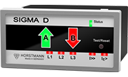
- Phase-selective short-circuit indicator with direction indicator
- Earth short-circuit monitoring with direction indication in NOSPE networks and OSPE networks with “open” rings
- Remote signal via relay contacts
- Self-powered, does not require an auxiliary power supply
- Internal battery for LED display
Sigma D+
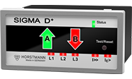
- Corresponds to Sigma D
- Additional earth shot location procedure for all neutral point treatments in MV networks
- Earth fault wiper application
- with summation current sensor
- without auxiliary power supply
Sigma D++
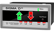
- Corresponds to the Sigma D+
- Earth fault wiper application
- without summation current sensor
- Auxiliary power supply 24V-230V AC/DC
Sigma DM
- Corresponds to the Sigma D++
- Remote signaling via RS485 and Modbus RTU
All devices can be programmed via DIP switches located behind the front of the device.
In addition, all Sigma D devices have a USB port on the front. The device can also or alternatively be parameterized via this connection using the Sigma Explorer software. This software offers numerous functions to support the commissioning and management of the device.